


Standard Sensors for detecting ferrous metals.
Proximity Sensor
Standard Sensors for Detecting Ferrous Metals under Standard Conditions
Wide array of variations. Ideal for a variety of applications.
Models with different frequencies are also available to prevent mutual interference.
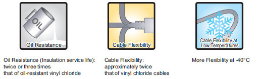
Superior environment resistance with standard cable made of oilresistant PVC and sensing surface made of material that resists cutting oil.
Useful to help prevent disconnection.
Cable protector provided as a standard feature.
2-Wire Models
Pre-wired Models with Oil-resistant Reinforced PUR Cables Added to the Lineup and Easy Differentiation with Orange Head
Lineup includes models with Smartclick pre-wired connectors for fast connection.

UL-recognized Models Available

Lineup includes models with self-diagnostic output to provide notification of failures and unstable detection conditions, such as coil burnout.
Contributes to preventive maintenance to keep the line from stopping.
Reduced wiring, fewer resources, and low power consumption contribute to environmentalism.
• Wiring work and amount of copper wire used reduced to two thirds of that required for 3-wire models.
• Current consumption drastically reduced to less than 10% (when a DC 2-wire model is compared with a DC 3-wire
model).
• Current consumption drastically reduced to less than 10% (when a DC 2-wire model is compared with a DC 3-wire
model).
3-Wire Models
Wide range of ambient operating temperatures: −40°C to 85°C (M8 to M30 models)
• Suitable for low-temperature and high-temperature applications, which are troublesome for photoelectric sensors.
Lineup includes models with flexible cable (M8 to M30 models)
2-Wire Models
Shielded DC 2-wire Models with No Self-diagnostic Output

| Ap- pear- ance | Sensing distance | Con- nection method | Cable specifi- cations | Po- lar- ity | Opera- tion mode | Pin ar- range- ment | Appli- cable con- nector code *2 | Model |
|---|---|---|---|---|---|---|---|---|
| M8 | 2 mm | M12 Pre- wired Smartclick Connector Models (0.3 m) | PUR (increased oil-resistant) | Yes | NO | 1: +V, 4: 0 V | H | E2E-X2D1-M1TGJ-U 0.3M |
| NC | 1: +V, 2: 0 V | E2E-X2D2-M1TGJ-U 0.3M | ||||||
| PVC (oil-resistant) | NO | 1: +V, 4: 0 V | G | E2E-X2D1-M1TGJ 0.3M | ||||
| Pre-wired Models (2 m) | PUR (increased oil-resistant) | NO | --- | --- | E2E-X2D1-U 2M | |||
| NC | E2E-X2D2-U 2M | |||||||
| PVC (oil-resistant) | NO | E2E-X2D1-N 2M | ||||||
| NC | E2E-X2D2-N 2M | |||||||
| M12 Connector Models | --- | NO | 1: +V, 4: 0 V | A | E2E-X2D1-M1G | |||
| NC | 1: +V, 2: 0 V | D | E2E-X2D2-M1G | |||||
| M8 Connector Models | --- | NO | 1: +V, 4: 0 V | I | E2E-X2D1-M3G | |||
| NC | 1: +V, 2: 0 V | E2E-X2D2-M3G | ||||||
| M12 | 3 mm | M12 Pre- wired Smartclick Connector Models (0.3 m) | PUR (increased oil-resistant) | Yes | NO | 1: +V, 4: 0 V | H | E2E-X3D1-M1TGJ-U 0.3M |
| NC | 1: +V, 2: 0 V | E2E-X3D2-M1TGJ-U 0.3M | ||||||
| PVC (oil-resistant) | NO | 1: +V, 4: 0 V | G | E2E-X3D1-M1TGJ 0.3M | ||||
| Pre-wired Models (2 m) | PUR (increased oil-resistant) | NO | --- | --- | E2E-X3D1-U 2M | |||
| NC | E2E-X3D2-U 2M | |||||||
| PVC (oil-resistant) | NO | E2E-X3D1-N 2M *1 | ||||||
| NC | E2E-X3D2-N 2M | |||||||
| M12 Connector Models | --- | NO | 1: +V, 4: 0 V | A | E2E-X3D1-M1G *1 | |||
| NC | 1: +V, 2: 0 V | D | E2E-X3D2-M1G | |||||
| M12 Standard Pre-wired Connector Models (0.3 m) | PVC (oil-resistant) | Yes | NO | 1: +V, 4: 0 V | A | E2E-X3D1-M1GJ 0.3M | ||
| NC | 1: +V, 2: 0 V | D | E2E-X3D2-M1GJ 0.3M | |||||
| No *3 | NO | (3, 4): (+V, 0 V) | C | E2E-X3D1-M1J-T 0.3M | ||||
| NC | (1, 2): (+V, 0 V) | D | --- | |||||
| M18 | 7 mm | M12 Pre- wired Smartclick Connector Models (0.3 m) | PUR (increased oil-resistant) | Yes | NO | 1: +V, 4: 0 V | H | E2E-X7D1-M1TGJ-U 0.3M |
| NC | 1: +V, 2: 0 V | E2E-X7D2-M1TGJ-U 0.3M | ||||||
| PVC (oil-resistant) | NO | 1: +V, 4: 0 V | G | E2E-X7D1-M1TGJ 0.3M | ||||
| Pre-wired Models (2 m) | PUR (increased oil-resistant) | NO | --- | --- | E2E-X7D1-U 2M | |||
| NC | E2E-X7D2-U 2M | |||||||
| PVC (oil-resistant) | NO | E2E-X7D1-N 2M *1 | ||||||
| NC | E2E-X7D2-N 2M | |||||||
| M12 Connector Models | --- | NO | 1: +V, 4: 0 V | A | E2E-X7D1-M1G *1 | |||
| NC | 1: +V, 2: 0 V | D | E2E-X7D2-M1G | |||||
| M12 Standard Pre-wired Connector Models (0.3 m) | PVC (oil-resistant) | Yes | NO | 1: +V, 4: 0 V | A | E2E-X7D1-M1GJ 0.3M | ||
| NC | 1: +V, 2: 0 V | D | E2E-X7D2-M1GJ 0.3M | |||||
| No *3 | NO | (3, 4): (+V, 0 V) | C | E2E-X7D1-M1J-T 0.3M | ||||
| NC | (1, 2): (+V, 0 V) | D | E2E-X7D2-M1J-T 0.3M | |||||
| M30 | 10 mm | M12 Pre- wired Smartclick Connector Models (0.3 m) | PUR (increased oil-resistant) | Yes | NO | 1: +V, 4: 0 V | H | E2E-X10D1-M1TGJ-U 0.3M |
| NC | 1: +V, 2: 0 V | E2E-X10D2-M1TGJ-U 0.3M | ||||||
| PVC (oil-resistant) | NO | 1: +V, 4: 0 V | G | E2E-X10D1-M1TGJ 0.3M | ||||
| Pre-wired Models (2 m) | PUR (increased oil-resistant) | NO | --- | --- | E2E-X10D1-U 2M | |||
| NC | E2E-X10D2-U 2M | |||||||
| PVC (oil-resistant) | NO | E2E-X10D1-N 2M *1 | ||||||
| NC | E2E-X10D2-N 2M | |||||||
| M12 Connector Models | --- | NO | 1: +V, 4: 0 V | A | E2E-X10D1-M1G *1 | |||
| NC | 1: +V, 2: 0 V | D | E2E-X10D2-M1G | |||||
| M12 Standard Pre-wired Connector Models (0.3 m) | PVC (oil-resistant) | Yes | NO | 1: +V, 4: 0 V | A | E2E-X10D1-M1GJ 0.3M | ||
| PVC (oil-resistant) | NC | 1: +V, 2: 0 V | D | E2E-X10D2-M1GJ 0.3M | ||||
| PVC (oil-resistant) | No *3 | NO | (3, 4): (+V, 0 V) | C | E2E-X10D1-M1J-T 0.3M | |||
| PVC (oil-resistant) | NC | (1, 2): (+V, 0 V) | D | E2E-X10D2-M1J-T 0.3M |
*1. Models with different frequencies are also available. The model number is E2E-X[]D15 (example: E2E-X3D15-N 2M).
*2. Refer to Data Sheet for details.
*3. The residual voltage for models without polarity is 5 V, so use caution concerning the connection load interface
conditions (e.g., PLC ON voltage).
Refer to Data Sheet.
Shielded DC 2-Wire UL-recognized Models with No Self-diagnostic Output
| Ap- pear- ance | Sensing distance | Connection method | Cable specifi- cations | Po- lar- ity | Opera- tion mode | Pin ar- range- ment | Appli- cable con- nector code * | Model |
|---|---|---|---|---|---|---|---|---|
| M8 | 2 mm | M12 Pre-wired Smartclick Connector Models (0.3 m) | PVC (oil- resistant) | Yes | NO | 1: +V, 4: 0 V | G | E2E-X2D1-M1TGJ-US 0.3M |
| NC | 1: +V, 2: 0 V | E2E-X2D2-M1TGJ-US 0.3M | ||||||
| Pre-wired Models (2 m) | NO | --- | --- | E2E-X2D1-US 2M | ||||
| NC | E2E-X2D2-US 2M | |||||||
| M12 | 3 mm | M12 Pre-wired Smartclick Connector Models (0.3 m) | NO | 1: +V, 4: 0 V | G | E2E-X3D1-M1TGJ-US 0.3M | ||
| NC | 1: +V, 2: 0 V | E2E-X3D2-M1TGJ-US 0.3M | ||||||
| Pre-wired Models (2 m) | NO | --- | --- | E2E-X3D1-US 2M | ||||
| NC | E2E-X3D2-US 2M | |||||||
| M18 | 7 mm | M12 Pre-wired Smartclick Connector Models (0.3 m) | NO | 1: +V, 4: 0 V | G | E2E-X7D1-M1TGJ-US 0.3M | ||
| NC | 1: +V, 2: 0 V | E2E-X7D2-M1TGJ-US 0.3M | ||||||
| Pre-wired Models (2 m) | NO | --- | --- | E2E-X7D1-US 2M | ||||
| NC | E2E-X7D2-US 2M | |||||||
| M30 | 10 mm | M12 Pre-wired Smartclick Connector Models (0.3 m) | NO | 1: +V, 4: 0 V | G | E2E-X10D1-M1TGJ-US 0.3M | ||
| NC | 1: +V, 2: 0 V | E2E-X10D2-M1TGJ-US 0.3M | ||||||
| Pre-wired Models (2 m) | NO | --- | --- | E2E-X10D1-US 2M | ||||
| NC | E2E-X10D2-US 2M |
* Refer to Data Sheet for details.
Unshielded DC 2-Wire Models with No Self-diagnosis Output

| Ap- pear- ance | Sensing distance | Con- nection method | Cable specifi- cations | Po- lar- ity | Opera- tion mode | Pin ar- range- ment | Appli- cable con- nector code *2 | Model |
|---|---|---|---|---|---|---|---|---|
| M8 | 4 mm | Pre-wired Models (2 m) | PVC (oil-resistant) | Yes | NO | --- | --- | E2E-X4MD1 2M |
| NC | E2E-X4MD2 2M | |||||||
| M12 Connector Models | --- | NO | 1: +V, 4: 0 V | A | E2E-X4MD1-M1G | |||
| NC | 1: +V, 2: 0 V | D | E2E-X4MD2-M1G | |||||
| M8 Connector Models | --- | NO | 1: +V, 4: 0 V | I | E2E-X4MD1-M3G | |||
| NC | 1: +V, 2: 0 V | E2E-X4MD2-M3G | ||||||
| M12 | 8 mm | M12 Pre-wired Smartclick Connector Models (0.3 m) | PVC (oil-resistant) | NO | 1: +V, 4: 0 V | G | E2E-X8MD1-M1TGJ 0.3M | |
| Pre-wired Models (2 m) | PVC (oil-resistant) | NO | --- | --- | E2E-X8MD1 2M *1 | |||
| NC | E2E-X8MD2 2M | |||||||
| M12 Connector Models | --- | NO | 1: +V, 4: 0 V | A | E2E-X8MD1-M1G *1 | |||
| NC | 1: +V, 2: 0 V | D | E2E-X8MD2-M1G | |||||
| M12 Standard Pre-wired Connector Models (0.3 m) | PVC (oil-resistant) | NO | 1: +V, 4: 0 V | A | E2E-X8MD1-M1GJ 0.3M | |||
| NC | 1: +V, 2: 0 V | D | --- | |||||
| M18 | 14 mm | M12 Pre-wired Smartclick Connector Models (0.3 m) | PVC (oil-resistant) | NO | 1: +V, 4: 0 V | G | E2E-X14MD1-M1TGJ 0.3M | |
| Pre-wired Models (2 m) | PVC (oil-resistant) | NO | --- | --- | E2E-X14MD1 2M *1 | |||
| NC | E2E-X14MD2 2M | |||||||
| M12 Connector Models | --- | NO | 1: +V, 4: 0 V | A | E2E-X14MD1-M1G *1 | |||
| NC | 1: +V, 2: 0 V | D | E2E-X14MD2-M1G | |||||
| M12 Standard Pre-wired Connector Models (0.3 m) | PVC (oil-resistant) | NO | 1: +V, 4: 0 V | A | E2E-X14MD1-M1GJ 0.3M | |||
| NC | 1: +V, 2: 0 V | D | E2E-X14MD2-M1GJ 0.3M | |||||
| M30 | 20 mm | M12 Pre-wired Smartclick Connector Models (0.3 m) | PVC (oil-resistant) | NO | 1: +V, 4: 0 V | G | E2E-X20MD1-M1TGJ 0.3M | |
| Pre-wired Models (2 m) | PVC (oil-resistant) | NO | --- | --- | E2E-X20MD1 2M *1 | |||
| NC | E2E-X20MD2 2M | |||||||
| M12 Connector Models | --- | NO | 1: +V, 4: 0 V | A | E2E-X20MD1-M1G *1 | |||
| NC | 1: +V, 2: 0 V | D | E2E-X20MD2-M1G | |||||
| M12 Standard Pre-wired Connector Models (0.3 m) | PVC (oil-resistant) | NO | 1: +V, 4: 0 V | A | E2E-X20MD1-M1GJ 0.3M | |||
| NC | 1: +V, 2: 0 V | D | --- |
*1. Models with different frequencies are also available. The model number is E2E-X[]D15 (example: E2E-X8MD15 2M).
*2. Refer to Data Sheet for details.
Unshielded DC 2-Wire UL-recognized Models with No Self-diagnostic Output
| Ap- pear- ance | Sensing distance | Con- nection method | Cable specifi- cations | Po- lar- ity | Opera- tion mode | Pin ar- range- ment | Appli- cable con- nector code * | Model |
|---|---|---|---|---|---|---|---|---|
| M8 | 4 mm | M12 Pre-wired Smartclick Connector Models (0.3 m) | PVC (oil- resistant) | Yes | NO | 1: +V, 4: 0 V | G | E2E-X4MD1-M1TGJ-US 0.3M |
| NC | 1: +V, 2: 0 V | E2E-X4MD2-M1TGJ-US 0.3M | ||||||
| Pre-wired Models (2 m) | NO | --- | --- | E2E-X4MD1-US 2M | ||||
| NC | E2E-X4MD2-US 2M | |||||||
| M12 | 8 mm | M12 Pre-wired Smartclick Connector Models (0.3 m) | NO | 1: +V, 4: 0 V | G | E2E-X8MD1-M1TGJ-US 0.3M | ||
| NC | 1: +V, 2: 0 V | E2E-X8MD2-M1TGJ-US 0.3M | ||||||
| Pre-wired Models (2 m) | NO | --- | --- | E2E-X8MD1-US 2M | ||||
| NC | E2E-X8MD2-US 2M | |||||||
| M18 | 14 mm | M12 Pre-wired Smartclick Connector Models (0.3 m) | NO | 1: +V, 4: 0 V | G | E2E-X14MD1-M1TGJ-US 0.3M | ||
| NC | 1: +V, 2: 0 V | E2E-X14MD2-M1TGJ-US 0.3M | ||||||
| Pre-wired Models (2 m) | NO | --- | --- | E2E-X14MD1-US 2M | ||||
| NC | E2E-X14MD2-US 2M | |||||||
| M30 | 20 mm | M12 Pre-wired Smartclick Connector Models (0.3 m) | NO | 1: +V, 4: 0 V | G | E2E-X20MD1-M1TGJ-US 0.3M | ||
| NC | 1: +V, 2: 0 V | E2E-X20MD2-M1TGJ-US 0.3M | ||||||
| Pre-wired Models (2 m) | NO | --- | --- | E2E-X20MD1-US 2M | ||||
| NC | E2E-X20MD2-US 2M |
* Refer to Data Sheet for details.
Shielded DC 2-Wire Models with Self-diagnosis Output
| Ap- pear- ance | Sensing distance | Con- nection method | Cable specifi- cations | Po- lar- ity | Opera- tion mode | Pin arrangement | Appli- cable con- nector code *2 | Model |
|---|---|---|---|---|---|---|---|---|
| M12 | 3 mm | Pre-wired Models (2 m) | PVC (oil- resistant) | Yes | NO | --- | --- | E2E-X3D1S 2M *1 |
| M12 Connector Models | --- | 2: +V and diagnostic output 3: 0 V 4: +V and control output | D | E2E-X3D1S-M1 | ||||
| M18 | 7 mm | Pre-wired Models (2 m) | PVC (oil- resistant) | --- | --- | E2E-X7D1S 2M *1 | ||
| M12 Connector Models | --- | 2: +V and diagnostic output 3: 0 V 4: +V and control output | D | E2E-X7D1S-M1 | ||||
| M30 | 10 mm | Pre-wired Models (2 m) | PVC (oil- resistant) | --- | --- | E2E-X10D1S 2M *1 | ||
| M12 Connector Models | --- | 2: +V and diagnostic output 3: 0 V 4: +V and control output | D | E2E-X10D1S-M1 |
*1. Models with different frequencies are also available. The model number is E2E-X[]D15S (example: E2E-X3D15S 2M).
*2. Refer to Data Sheet for details.
Unshielded DC 2-Wire Models with Self-diagnosis Output
| Ap- pear- ance | Sensing distance | Con- nection method | Cable specifi- cations | Po- lar- ity | Opera- tion mode | Pin arrangement | Appli- cable con- nector code *2 | Model |
|---|---|---|---|---|---|---|---|---|
| M12 | 8 mm | Pre-wired Models (2 m) | PVC (oil- resistant) | Yes | NO | --- | --- | E2E-X8MD1S 2M *1 |
| M12 Connector Models | --- | 2: +V and diagnostic output 3: 0 V 4: +V and control output | D | E2E-X8MD1S-M1 | ||||
| M18 | 14 mm | Pre-wired Models (2 m) | PVC (oil- resistant) | --- | --- | E2E-X14MD1S 2M *1 | ||
| M12 Connector Models | --- | 2: +V and diagnostic output 3: 0 V 4: +V and control output | D | E2E-X14MD1S-M1 | ||||
| M30 | 20 mm | Pre-wired Models (2 m) | PVC (oil- resistant) | --- | --- | E2E-X20MD1S 2M *1 | ||
| M12 Connector Models | --- | 2: +V and diagnostic output 3: 0 V 4: +V and control output | D | E2E-X20MD1S-M1 |
*1. Models with different frequencies are also available. The model number is E2E-X[]MD15S (example: E2E-X8MD15S 2M).
*2. Refer to Data Sheet for details.
Connector Pin Assignments of DC 2-Wire Models
The connector pin assignments of each New E2E DC 2-Wire Model conform to IEC 947-5-2 Table III. (Only DC 2-Wire Models have been changed in comparison to the previous models.)
The following models with conventional connector pin assignments are available as well. (Only NO Models can be used.)
The cable at the below should also be used if the XW3A-P[]45-G11 Connector Junction Box is already being used.
| Cable length | Model |
|---|---|
| 500 mm | XS2W-D421-BY1 |
Models with conventional connector pin assignments are available as well.
| Appearance | Model | ||||
|---|---|---|---|---|---|
| NO | Applicable connector code * | NC | Applicable connector code * | ||
 | M8 | E2E-X2D1-M1 | C | E2E-X2D2-M1 | D |
| M12 | E2E-X3D1-M1 | C | E2E-X3D2-M1 | D | |
| M18 | E2E-X7D1-M1 | C | E2E-X7D2-M1 | D | |
| M30 | E2E-X10D1-M1 | C | E2E-X10D2-M1 | D | |
 | M8 | E2E-X4MD1-M1 | C | E2E-X4MD2-M1 | D |
| M12 | E2E-X8MD1-M1 | C | E2E-X8MD2-M1 | D | |
| M18 | E2E-X14MD1-M1 | C | E2E-X14MD2-M1 | D | |
| M30 | E2E-X20MD1-M1 | C | E2E-X20MD2-M1 | D | |
* Refer to Data Sheet for details.
AC 2-Wire Models Shielded Models
| Appear- ance | Sensing distance | Connection method | Cable specifications | Opera- tion mode | Pin arrangement | Applicable connector code *2 | Model |
|---|---|---|---|---|---|---|---|
| M8 | 1.5 mm | Pre-wired Models (2 m) | PVC (oil-resistant) | NO | --- | --- | E2E-X1R5Y1 2M |
| NC | E2E-X1R5Y2 2M | ||||||
| M12 | 2 mm | Pre-wired Models (2 m) | PVC (oil-resistant) | NO | --- | --- | E2E-X2Y1 2M *1 |
| NC | E2E-X2Y2 2M | ||||||
| M12 Connector Models | --- | NO | (3, 4): (AC, AC) | E | E2E-X2Y1-M1 | ||
| NC | (1, 2): (AC, AC) | F | E2E-X2Y2-M1 | ||||
| M18 | 5 mm | Pre-wired Models (2 m) | PVC (oil-resistant) | NO | --- | --- | E2E-X5Y1 2M *1 |
| NC | E2E-X5Y2 2M | ||||||
| M12 Connector Models | --- | NO | (3, 4): (AC, AC) | E | E2E-X5Y1-M1 | ||
| NC | (1, 2): (AC, AC) | F | E2E-X5Y2-M1 | ||||
| M30 | 10 mm | Pre-wired Models (2 m) | PVC (oil-resistant) | NO | --- | --- | E2E-X10Y1 2M *1 |
| NC | E2E-X10Y2 2M | ||||||
| M12 Connector Models | --- | NO | (3, 4): (AC, AC) | E | E2E-X10Y1-M1 | ||
| NC | (1, 2): (AC, AC) | F | E2E-X10Y2-M1 |
*1. Models with different frequencies are also available. The model number is E2E-X[]Y[]5 (example: E2E-X5Y15 2M).
*2. Refer to Data Sheet for details.
Unshielded Models
| Appear- ance | Sensing distance | Connection method | Cable specifications | Opera- tion mode | Pin arrangement | Applicable connector code *2 | Model |
|---|---|---|---|---|---|---|---|
| M8 | 2 mm | Pre-wired Models (2 m) | PVC (oil-resistant) | NO | --- | --- | E2E-X2MY1 2M |
| NC | E2E-X2MY2 2M | ||||||
| M12 | 5 mm | Pre-wired Models (2 m) | PVC (oil-resistant) | NO | --- | --- | E2E-X5MY1 2M *1 |
| NC | E2E-X5MY2 2M | ||||||
| M12 Connector Models | --- | NO | (3, 4): (AC, AC) | E | E2E-X5MY1 2M | ||
| NC | (1, 2): (AC, AC) | F | E2E-X5MY2-M1 | ||||
| M18 | 10 mm | Pre-wired Models (2 m) | PVC (oil-resistant) | NO | --- | --- | E2E-X10MY1 2M *1 |
| NC | E2E-X10MY2 2M | ||||||
| M12 Connector Models | --- | NO | (3, 4): (AC, AC) | E | E2E-X10MY1-M1 | ||
| NC | (1, 2): (AC, AC) | F | E2E-X10MY2-M1 | ||||
| M30 | 18 mm | Pre-wired Models (2 m) | PVC (oil-resistant) | NO | --- | --- | E2E-X18MY1 2M *1 |
| NC | E2E-X18MY2 2M | ||||||
| M12 Connector Models | --- | NO | (3, 4): (AC, AC) | E | E2E-X18MY1-M1 | ||
| NC | (1, 2): (AC, AC) | F | E2E-X18MY2-M1 |
*1. Models with different frequencies are also available. The model number is E2E-X[]MY[]5 (example: E2E-X5MY15 2M).
*2. Refer to Data Sheet for details.
AC 2-Wire Models Shielded Models (There are no unshielded models.)
| Appear- ance | Sensing distance | Connection method | Cable specifications | Operation mode | Pin arrange- ment | Applicable connector code | Model |
|---|---|---|---|---|---|---|---|
| M12 | 3 mm | Pre-wired Models (2 m) | PVC (oil-resistant) | NO | --- | --- | E2E-X3T1 2M |
| M18 | 7 mm | Pre-wired Models (2 m) | PVC (oil-resistant) | --- | --- | E2E-X7T1 2M | |
| M30 | 10 mm | Pre-wired Models (2 m) | PVC (oil-resistant) | --- | --- | E2E-X10T1 2M |
Note: Not compliant with CE.
3-Wire Models
Shielded DC 3-Wire Models
| Ap- pear- ance | Sensing distance | Con- nection method | Cable specifi- cations | Opera- tion mode | Pin arrange- ment | Appli- cable con- nector code *2 | Model | |
|---|---|---|---|---|---|---|---|---|
| NPN output | PNP output | |||||||
| M8 | 1.5 mm | Pre-wired Models (2 m) | PVC (oil- resistant) | NO | --- | --- | E2E-X1R5E1 2M | E2E-X1R5F1 2M |
| PVC (oil- resistant) | NC | E2E-X1R5E2 2M | E2E-X1R5F2 2M | |||||
| M12 Connector Models | --- | NO | 1: +V, 3: 0 V, 4: Control output | B | E2E-X1R5E1-M1 | E2E-X1R5F1-M1 | ||
| NC | 1: +V, 3: 0 V, 2: Control output | D | E2E-X1R5E2-M1 | E2E-X1R5F2-M1 | ||||
| M8 Connector Models | --- | NO | 1: +V, 3: 0 V, 4: Control output | I | E2E-X1R5E1-M3 | E2E-X1R5F1-M3 | ||
| NC | 1: +V, 3: 0 V, 2: Control output | E2E-X1R5E2-M3 | E2E-X1R5F2-M3 | |||||
| M12 | 2 mm | Pre-wired Models (2 m) | PVC (oil- resistant) | NO | --- | --- | E2E-X2E1 2M *1 | E2E-X2F1 2M *1 |
| NC | E2E-X2E2 2M | E2E-X2F2 2M | ||||||
| M12 Connector Models | --- | NO | 1: +V, 3: 0 V, 4: Control output | B | E2E-X2E1-M1 | E2E-X2F1-M1 | ||
| NC | 1: +V, 3: 0 V, 2: Control output | D | E2E-X2E2-M1 | E2E-X2F2-M1 | ||||
| M18 | 5 mm | Pre-wired Models (2 m) | PVC (oil- resistant) | NO | --- | --- | E2E-X5E1 2M *1 | E2E-X5F1 2M *1 |
| NC | E2E-X5E2 2M | E2E-X5F2 2M | ||||||
| M12 Connector Models | --- | NO | 1: +V, 3: 0 V, 4: Control output | B | E2E-X5E1-M1 | E2E-X5F1-M1 | ||
| NC | 1: +V, 3: 0 V, 2: Control output | D | E2E-X5E2-M1 | E2E-X5F2-M1 | ||||
| M30 | 10 mm | Pre-wired Models (2 m) | PVC (oil- resistant) | NO | --- | --- | E2E-X10E1 2M *1 | E2E-X10F1 2M |
| NC | E2E-X10E2 2M | E2E-X10F2 2M | ||||||
| M12 Connector Models | --- | NO | 1: +V, 3: 0 V, 4: Control output | B | E2E-X10E1-M1 | E2E-X10F1-M1 | ||
| NC | 1: +V, 3: 0 V, 2: Control output | D | E2E-X10E2-M1 | E2E-X10F2-M1 | ||||
*1. Models with different frequencies are also available. The model number is E2E-X[][][]5 (example: E2E-X5E15 2M).
*2. Refer to Data Sheet for details.
Unshielded DC 3-Wire Models
| Ap- pear- ance | Sensing distance | Con- nection method | Cable specifi- cations | Opera- tion mode | Pin arrange- ment | Appli- cable con- nector code *2 | Model | |
|---|---|---|---|---|---|---|---|---|
| NPN output | PNP output | |||||||
| M8 | 2 mm | Pre-wired Models (2 m) | PVC (oil- resistant) | NO | --- | --- | E2E-X2ME1 2M | E2E-X2MF1 2M |
| NC | E2E-X2ME2 2M | E2E-X2MF2 2M | ||||||
| M12 Connector Models | --- | NO | 1: +V, 3: 0 V, 4: Control output | B | E2E-X2ME1-M1 | E2E-X2MF1-M1 | ||
| NC | 1: +V, 3: 0 V, 2: Control output | D | E2E-X2ME2-M1 | E2E-X2MF2-M1 | ||||
| M8 Connector Models | --- | NO | 1: +V, 3: 0 V, 4: Control output | I | E2E-X2ME1-M3 | E2E-X2MF1-M3 | ||
| NC | 1: +V, 3: 0 V, 2: Control output | E2E-X2ME2-M3 | E2E-X2MF2-M3 | |||||
| M12 | 5 mm | Pre-wired Models (2 m) | PVC (oil- resistant) | NO | --- | --- | E2E-X5ME1 2M *1 | E2E-X5MF1 2M |
| NC | E2E-X5ME2 2M | E2E-X5MF2 2M | ||||||
| M12 Connector Models | --- | NO | 1: +V, 3: 0 V, 4: Control output | B | E2E-X5ME1-M1 | E2E-X5MF1-M1 | ||
| NC | 1: +V, 3: 0 V, 2: Control output | D | E2E-X5ME2-M1 | E2E-X5MF2-M1 | ||||
| M18 | 10 mm | Pre-wired Models (2 m) | PVC (oil- resistant) | NO | --- | --- | E2E-X10ME1 2M *1 | E2E-X10MF1 2M |
| NC | E2E-X10ME2 2M | E2E-X10MF2 2M | ||||||
| M12 Connector Models | --- | NO | 1: +V, 3: 0 V, 4: Control output | B | E2E-X10ME1-M1 | E2E-X10MF1-M1 | ||
| NC | 1: +V, 3: 0 V, 2: Control output | D | E2E-X10ME2-M1 | E2E-X10MF2-M1 | ||||
| M30 | 18 mm | Pre-wired Models (2 m) | PVC (oil- resistant) | NO | --- | --- | E2E-X18ME1 2M *1 | E2E-X18MF1 2M |
| NC | E2E-X18ME2 2M | E2E-X18MF2 2M | ||||||
| M12 Connector Models | --- | NO | 1: +V, 3: 0 V, 4: Control output | B | E2E-X18ME1-M1 | E2E-X18MF1-M1 | ||
| NC | 1: +V, 3: 0 V, 2: Control output | D | E2E-X18ME2-M1 | E2E-X18MF2-M1 | ||||
*1. Models with different frequencies are also available. The model number is E2E-X[]M[][]5 (example: E2E-X5ME15 2M).
*2. Refer to Data Sheet for details.
Sensor I/O Connectors (Sockets on One Cable End)
Model for Connectors and Pre-wired Connectors: A Connector is not provided with the Sensor. Be sure to order a Connector separately.
| Connector | Applicable Proximity Sensor model number | |||
|---|---|---|---|---|
| Screw | Appearance *1 | Cable length 2m | Cable length 5m | |
| CablConnector model number | CablConnector model number | |||
| M12 | Straight | XS2F-D421-DA0-F | XS2F-D421-GA0-F | E2E-X[]D1-M1G(J) |
| L-shape | XS2F-D422-DA0-F | XS2F-D422-GA0-F | ||
| Straight | XS2F-D421-DC0-F | XS2F-D421-GC0-F | E2E-X[]E1-M1 E2E-X[]F1-M1 | |
| L-shape | XS2F-D422-DC0-F | XS2F-D422-GC0-F | ||
| Straight | XS2F-D421-DD0 | XS2F-D421-GD0 | E2E-X[]D1-M1J-T | |
| E2E-X[]D1-M1 | ||||
| L-shape | XS2F-D422-DD0 | XS2F-D422-GD0 | E2E-X[]D1-M1J-T | |
| E2E-X[]D1-M1 | ||||
| Straight | XS2F-D421-D80-F | XS2F-D421-G80-F | E2E-X[]D2-M1G(J) | |
| E2E-X[]D2-M1J-T | ||||
| E2E-X[]D2-M1 | ||||
| E2E-X[]D1S-M1 | ||||
| E2E-X[]E2-M1 E2E-X[]F2-M1 | ||||
| L-shape | XS2F-D422-D80-F | XS2F-D422-G80-F | E2E-X[]D2-M1G(J) | |
| E2E-X[]D2-M1J-T | ||||
| E2E-X[]D2-M1 | ||||
| E2E-X[]D1S-M1 | ||||
| E2E-X[]E2-M1 E2E-X[]F2-M1 | ||||
| Straight | XS2F-A421-DB0-F | XS2F-A421-GB0-F | E2E-X[]Y1-M1 | |
| L-shape | XS2F-A422-DB0-F | XS2F-A422-GB0-F | ||
| Straight | XS2F-A421-D90-F | XS2F-A421-G90-F | E2E-X[]Y2-M1 | |
| Smartclick Connector, Straight | XS5F-D421-D80-F | XS5F-D421-G80-F | E2E-X[]D1-M1TGJ(-US) | |
| E2E-X[]D2-M1TGJ-US | ||||
| Smartclick Connector, Straight Oil-resistant Reinforced Cables | XS5F-D421-D80-P | XS5F-D421-G80-P | E2E-X[]D1-M1TGJ-U | |
| E2E-X[]D2-M1TGJ-U | ||||
| M8 | Straight | XS3F-M421-402-A | XS3F-M421-405-A | E2E-X[]D1-M3G |
| E2E-X[]D2-M3G | ||||
| E2E-X[]E1-M3 E2E-X[]F1-M3 | ||||
| E2E-X[]E2-M3 E2E-X[]F2-M3 | ||||
| L-shape | XS3F-M422-402-A | XS3F-M422-405-A | E2E-X[]D1-M3G | |
| E2E-X[]D2-M3G | ||||
| E2E-X[]E1-M3 E2E-X[]F1-M3 | ||||
| E2E-X[]E2-M3 E2E-X[]F2-M3 | ||||
Note: Refer to Introduction to Sensor I/O Connectors/Sensor Controllers for details and for information on Cable length
and Robotics Cables.
*1. Images of straight and L-shaped connectors.
and Robotics Cables.
*1. Images of straight and L-shaped connectors.

*2. Refer to Connection Diagrams on Data Sheet for information on Proximity Sensor and I/O Connector connections.
E2E-X[]D[] DC 2-Wire Models
| Size | M8 | M12 | |||
|---|---|---|---|---|---|
| Shielded | Shielded | Unshielded | Shielded | Unshielded | |
| Model | E2E-X2D[] | E2E-X4MD[] | E2E-X3D[] | E2E-X8MD[] | |
| Sensing distance | 2 mm ±10% | 4 mm ±10% | 3 mm ±10% | 8 mm ±10% | |
| Set distance *1 | 0 to 1.6 mm | 0 to 3.2 mm | 0 to 2.4 mm | 0 to 6.4 mm | |
| Differential travel | 15% max. of sensing distance | 10% max. of sensing distance | |||
| Detectable object | Ferrous metal (The sensing distance decreases with non-ferrous metal. Refer to Engineering Data on Data Sheet.) | ||||
| Standard sensing object | Iron, 8 × 8 × 1 mm | Iron, 20 × 20 × 1 mm | Iron, 12 × 12 × 1 mm | Iron, 30 × 30 × 1 mm | |
| Response frequency *2 | 1.5 kHz | 1 kHz | 0.8 kHz | ||
| Power supply voltage (operating voltage range) | Standard Models: 12 to 24 VDC, ripple (p-p): 10% max. (10 to 30 VDC) US Models and Connector Models Used as UL-certified Models: 12 to 24 VDC, ripple (p-p): 10% max. (The operating voltage range is also the same.) *3 | ||||
| Leakage current | 0.8 mA max. | ||||
| Control output | Load current | 3 to 100 mA, Diagnostic output: 50 mA for -D1(5)S Models | |||
| Residual voltage *4 | 3 V max. (Load current: 100 mA, Cable length: 2 m, M1J-T Models only: 5 V max.) | ||||
| Indicators | D1 Models: Operation indicator (red) and setting indicator (green) D2 Models: Operation indicator (red) | ||||
| Operation mode (with sensing object approaching) | D1 Models: NO D2 Models: NC Refer to the timing charts under I/O Circuit Diagrams on Data Sheet for details. | ||||
| Diagnostic output delay | 0.3 to 1 s | ||||
| Protection circuits | Surge suppressor, Load short-circuit protection (for control and diagnostic output) | ||||
| Ambient temperature range | Operating: -25 to 70°C, Storage: -40 to 85°C (with no icing or condensation) | ||||
| Ambient humidity range | Operating/storage: 35% to 95% (with no condensation) | ||||
| Temperature influence | ±15% max. of sensing distance at 23°C in the temperature range of -25 to 70°C | ±10% max. of sensing distance at 23°C in the temperature range of -25 to 70°C | |||
| Voltage influence | ±1% max. of sensing distance at rated voltage in the rated voltage ±15% range | ||||
| Insulation resistance | 50 MΩ min. (at 500 VDC) between current-carrying parts and case | ||||
| Dielectric strength | 1000 VAC, 50/60 Hz for 1 minute between current carry parts and case | ||||
| Vibration resistance | Destruction: 10 to 55 Hz, 1.5-mm double amplitude for 2 hours each in X, Y, and Z directions | ||||
| Shock resistance | Destruction: 500 m/s2 10 times each in X, Y, and Z directions | Destruction: 1,000 m/s2 10 times each in X, Y, and Z directions | |||
| Degree of protection | Pre-wired Models: IEC 60529 IP67, in-house standards: oil-resistant Connector Models: IEC 60529 IP67 | ||||
| Connection method | Pre-wired Models (Standard cable length: 2 m), Connector Models, or Pre-wired Connector Models (Standard cable length: 0.3 m) | ||||
| Weight (packed state) | Pre-wired Models | Approx. 60 g | Approx. 70 g | ||
| Pre-wired Connector Models | --- | Approx. 40 g | |||
| Connector Models | Approx. 15 g | Approx. 25 g | |||
| Materi- als | Case | Stainless steel (SUS303) | Nickel-plated brass | ||
| Sensing surface | PBT | ||||
| Clamping nuts | Nickel-plated brass | ||||
| Toothed washer | Zinc-plated iron | ||||
| Accessories | Instruction manual | ||||
| Size | M18 | M30 | |||
|---|---|---|---|---|---|
| Shielded | Shielded | Unshielded | Shielded | Unshielded | |
| Model | E2E-X7D[] | E2E-X14MD[] | E2E-X10D[] | E2E-X20MD[] | |
| Sensing distance | 7 mm ±10% | 14 mm ±10% | 10 mm ±10% | 20 mm ±10% | |
| Set distance *1 | 0 to 5.6 mm | 0 to 11.2 mm | 0 to 8 mm | 0 to 16 mm | |
| Differential travel | 10% max. of sensing distance | ||||
| Detectable object | Ferrous metal (The sensing distance decreases with non-ferrous metal. Refer to Engineering Data on Data Sheet.) | ||||
| Standard sensing object | Iron, 18 × 18 × 1 mm | Iron, 30 × 30 × 1 mm | Iron, 54 × 54 × 1 mm | ||
| Response frequency *2 | 0.5 kHz | 0.4 kHz | 0.1 kHz | ||
| Power supply voltage (operating voltage range) | Standard Models: 12 to 24 VDC, ripple (p-p): 10% max. (10 to 30 VDC) US Models and Connector Models Used as UL-certified Models: 12 to 24 VDC, ripple (p-p): 10% max. (The operating voltage range is also the same.) *3 | ||||
| Leakage current | 0.8 mA max. | ||||
| Control output | Load current | 3 to 100 mA, Diagnostic output: 50 mA for -D1(5)S Models | |||
| Residual voltage *4 | 3 V max. (Load current: 100 mA, Cable length: 2 m, M1J-T Models only: 5 V max.) | ||||
| Indicators | D1 Models: Operation indicator (red) and setting indicator (green) D2 Models: Operation indicator (red) | ||||
| Operation mode (with sensing object approaching) | D1 Models: NO D2 Models: NC Refer to the timing charts under I/O Circuit Diagrams on Data Sheet for details. | ||||
| Diagnostic output delay | 0.3 to 1 s | ||||
| Protection circuits | Surge suppressor, Load short-circuit protection (for control and diagnostic output) | ||||
| Ambient temperature range | Operating: -25 to 70°C, Storage: -40 to 85°C (with no icing or condensation) | ||||
| Ambient humidity range | Operating/storage: 35% to 95% (with no condensation) | ||||
| Temperature influence | ±10% max. of sensing distance at 23°C in the temperature range of -25 to 70°C | ||||
| Voltage influence | ±1% max. of sensing distance at rated voltage in the rated voltage ±15% range | ||||
| Insulation resistance | 50 MΩ min. (at 500 VDC) between current-carrying parts and case | ||||
| Dielectric strength | 1000 VAC, 50/60 Hz for 1 minute between current carry parts and case | ||||
| Vibration resistance | Destruction: 10 to 55 Hz, 1.5-mm double amplitude for 2 hours each in X, Y, and Z directions | ||||
| Shock resistance | Destruction: 1,000 m/s2 10 times each in X, Y, and Z directions | ||||
| Degree of protection | Pre-wired Models: IEC 60529 IP67, in-house standards: oil-resistant Connector Models: IEC 60529 IP67 | ||||
| Connection method | Pre-wired Models (Standard cable length: 2 m), Connector Models, or Pre-wired Connector Models (Standard cable length: 0.3 m) | ||||
| Weight (packed state) | Pre-wired Models | Approx. 130 g | Approx. 175 g | ||
| Pre-wired Connector Models | Approx. 70 g | Approx. 110 g | |||
| Connector Models | Approx. 40 g | Approx. 90 g | |||
| Materi- als | Case | Nickel-plated brass | |||
| Sensing surface | PBT | ||||
| Clamping nuts | Nickel-plated brass | ||||
| Toothed washer | Zinc-plated iron | ||||
| Accessories | Instruction manual | ||||
*1. Use the E2E within the range in which the setting indicator (green LED) is ON (except D2 Models).
*2. The response frequency is an average value.
Measurement conditions are as follows: standard sensing object, a distance of twice the standard sensing object,
and a set distance of half the sensing distance.
*3. For the information on UL-certified connector models, refer to your OMRON website.
*4. The residual voltage of each M1J-T Model is 5 V. When connecting to a device, make sure that the device can
withstand the residual voltage. (Refer to page 26 for details.)
E2E-X[]Y[] AC 2-Wire Models
| Size | M8 | M12 | |||
|---|---|---|---|---|---|
| Shielded | Shielded | Unshielded | Shielded | Unshielded | |
| Model | E2E-X1R5Y[] | E2E-X2MY[] | E2E-X2Y[] | E2E-X5MY[] | |
| Sensing distance | 1.5 mm ±10% | 2 mm ±10% | 5 mm ±10% | ||
| Set distance | 0 to 1.2 mm | 0 to 1.6 mm | 0 to 4 mm | ||
| Differential travel | 10% max. of sensing distance | ||||
| Detectable object | Ferrous metal (The sensing distance decreases with non-ferrous metal. Refer to Engineering Data on Data Sheet.) | ||||
| Standard sensing object | Iron, 8 × 8 × 1 mm | Iron, 12 × 12 × 1 mm | Iron, 15 × 15 × 1 mm | ||
| Response frequency | 25 Hz | ||||
| Power supply voltage (operating voltage range) *1 | 24 to 240 VAC (20 to 264 VAC), 50/60 Hz | ||||
| Leakage current | 1.7 mA max. | ||||
| Control output | Load current *2 | 5 to 100 mA | 5 to 200 mA | ||
| Residual voltage | Refer to Engineering Data on Data Sheet. | ||||
| Indicators | Operation indicator (red) | ||||
| Operation mode (with sensing object approaching) | Y1 Models: NO Y2 Models: NC Refer to the timing charts under I/O Circuit Diagrams on Data Sheet for details. | ||||
| Protection circuits | Surge suppressor | ||||
| Ambient temperature range *1 *2 | Operating/Storage: -25 to 70°C (with no icing or condensation) | Operating/Storage: -40 to 85°C (with no icing or condensation) | |||
| Ambient humidity range | Operating/storage: 35% to 95% (with no condensation) | ||||
| Temperature influence | ±10% max. of sensing distance at 23°C in the temperature range of -25 to 70°C | ±15% max. of sensing distance at 23°C in the temperature range of -40 to 85°C, ±10% max. of sensing distance at 23°C in the temperature range of -25 to 70°C | |||
| Voltage influence | ±1% max. of sensing distance at rated voltage in the rated voltage ±15% range | ||||
| Insulation resistance | 50 MΩ min. (at 500 VDC) between current-carrying parts and case | ||||
| Dielectric strength | 4,000 VAC (M8 Models: 2,000 VAC), 50/60 Hz for 1 min between current-carrying parts and case | ||||
| Vibration resistance | Destruction: 10 to 55 Hz, 1.5-mm double amplitude for 2 hours each in X, Y, and Z directions | ||||
| Shock resistance | Destruction: 500 m/s2 10 times each in X, Y, and Z directions | Destruction: 1,000 m/s2 10 times each in X, Y, and Z directions | |||
| Degree of protection | Pre-wired Models: IEC 60529 IP67, in-house standards: oil-resistant Connector Models: IEC 60529 IP67 | ||||
| Connection method | Pre-wired Models (Standard cable length: 2 m) and Connector Models | ||||
| Weight (packed state) | Pre-wired Models Model | Approx. 60 g | Approx. 70 g | ||
| Connector Models | Approx. 15 g | Approx. 25 g | |||
| Materials | Case | Stainless steel (SUS303) | Nickel-plated brass | ||
| Sensing surface | PBT | ||||
| Clamping nuts | Nickel-plated brass | ||||
| Toothed washer | Zinc-plated iron | ||||
| Accessories | Instruction manual | ||||
| Size | M18 | M30 | |||
|---|---|---|---|---|---|
| Shielded | Shielded | Unshielded | Shielded | Unshielded | |
| Model | E2E-X5Y[] | E2E-X10MY[] | E2E-X10Y[] | E2E-X18MY[] | |
| Sensing distance | 5 mm ±10% | 10 mm ±10% | 18 mm ±10% | ||
| Set distance | 0 to 4 mm | 0 to 8 mm | 0 to 14 mm | ||
| Differential travel | 10% max. of sensing distance | ||||
| Detectable object | Ferrous metal (The sensing distance decreases with non-ferrous metal. Refer to Engineering Data on Data Sheet.) | ||||
| Standard sensing object | Iron, 18 × 18 × 1 mm | Iron, 30 × 30 × 1 mm | Iron, 54 × 54 × 1 mm | ||
| Response frequency | 25 Hz | ||||
| Power supply voltage (operating voltage range) *1 | 24 to 240 VAC (20 to 264 VAC), 50/60 Hz | ||||
| Leakage current | 1.7 mA max. | ||||
| Control output | Load current *2 | 5 to 300 mA | |||
| Residual voltage | Refer to Engineering Data on Data Sheet. | ||||
| Indicators | Operation indicator (red) | ||||
| Operation mode (with sensing object approaching) | Y1 Models: NO Y2 Models: NC Refer to the timing charts under I/O Circuit Diagrams on Data Sheet for details. | ||||
| Protection circuits | Surge suppressor | ||||
| Ambient temperature range *1 *2 | Operating/Storage: -40 to 85°C (with no icing or condensation) | ||||
| Ambient humidity range | Operating/storage: 35% to 95% (with no condensation) | ||||
| Temperature influence | ±15% max. of sensing distance at 23°C in the temperature range of -40 to 85°C, ±10% max. of sensing distance at 23°C in the temperature range of -25 to 70°C | ||||
| Voltage influence | ±1% max. of sensing distance at rated voltage in the rated voltage ±15% range | ||||
| Insulation resistance | 50 MΩ min. (at 500 VDC) between current-carrying parts and case | ||||
| Dielectric strength | 4,000 VAC (M8 Models: 2,000 VAC), 50/60 Hz for 1 min between current-carrying parts and case | ||||
| Vibration resistance | Destruction: 10 to 55 Hz, 1.5-mm double amplitude for 2 hours each in X, Y, and Z directions | ||||
| Shock resistance | Destruction: 1,000 m/s2 10 times each in X, Y, and Z directions | ||||
| Degree of protection | Pre-wired Models: IEC 60529 IP67, in-house standards: oil-resistant Connector Models: IEC 60529 IP67 | ||||
| Connection method | Pre-wired Models (Standard cable length: 2 m) and Connector Models | ||||
| Weight (packed state) | Pre-wired Models Model | Approx. 130 g | Approx. 175 g | ||
| Connector Models | Approx. 40 g | Approx. 90 g | |||
| Materials | Case | Stainless steel (SUS303) | Nickel-plated brass | ||
| Sensing surface | PBT | ||||
| Clamping nuts | Nickel-plated brass | ||||
| Toothed washer | Zinc-plated iron | ||||
| Accessories | Instruction manual | ||||
*1. When supplying 24 VAC to any of the above models, make sure that the operating ambient temperature range is at
least −25°C.
*2. When using an M18 or M30 Connector Model at an ambient temperature between 70 and 85°C, make sure that the
Sensor has a control output (load current) of 5 to 200 mA max.
E2E-X[]T1 AC/DC 2-Wire Models
| Size | M12 | M18 | M30 | |
|---|---|---|---|---|
| Shielded | Shielded | |||
| Model | E2E-X3T1 | E2E-X7T1 | E2E-X10T1 | |
| Sensing distance | 3 mm ±10% | 7 mm ±10% | 10 mm ±10% | |
| Set distance | 0 to 2.4 mm | 0 to 5.6 mm | 0 to 8 mm | |
| Differential travel | 10% max. of sensing distance | |||
| Detectable object | Ferrous metal (The sensing distance decreases with non-ferrous metal. Refer to Engineering Data on Data Sheet.) | |||
| Standard sensing object | Iron, 12 × 12 × 1 mm | Iron, 18 × 18 × 1 mm | Iron, 30 × 30 × 1 mm | |
| Response frequency *1 | DC | 1 kHz | 0.5 kHz | 0.4 kHz |
| AC | 25 Hz | |||
| Power supply voltage (operating voltage range) *2 | 24 to 240 VDC (20 to 264 VDC) 48 to 240 VAC (40 to 264 VAC) | |||
| Leakage current | DC: 1 mA max. AC: 2 mA max. | |||
| Control output | Load current | 5 to 100 mA | ||
| Residual voltage | DC: 6 V max. (Load current: 100 mA, Cable length: 2 m) AC: 10 V max. (Load current: 5 mA, Cable length: 2 m) | |||
| Indicators | Operation indicator (red), Setting indicator (green) | |||
| Operation mode (with sensing object approaching) | NO (Refer to the timing charts under I/O Circuit Diagrams on Data Sheet for details.) | |||
| Protection circuits | Load short-circuit protection (20 to 40 VDC only), Surge suppressor | |||
| Ambient temperature range | Operating: -25 to 70°C, Storage: -40 to 85°C (with no icing or condensation) | |||
| Ambient humidity range | Operating/Storage: 35% to 95% (with no condensation) | |||
| Temperature influence | ±10% max. of sensing distance at 23°C in the temperature range of -25 to 70°C | |||
| Voltage influence | ±1% max. of sensing distance at rated voltage in the rated voltage ±15% range | |||
| Insulation resistance | 50 MΩ min. (at 500 VDC) between current-carrying parts and case | |||
| Dielectric strength | 4,000 VAC, 50/60 Hz for 1 minute between current-carrying parts and case | |||
| Vibration resistance | Destruction: 10 to 55 Hz, 1.5-mm double amplitude for 2 hours each in X, Y, and Z directions | |||
| Shock resistance | Destruction: 1,000 m/s2 10 times each in X, Y, and Z directions | |||
| Degree of protection | IEC 60529 IP67, in-house standards: oil-resistant | |||
| Connection method | Pre-wired Models (Standard cable length: 2 m) | |||
| Weight (packed state) | Approx. 80 g | Approx. 140 g | Approx. 190 g | |
| Materials | Case | Nickel-plated brass | ||
| Sensing surface | PBT | |||
| Clamping nuts | Nickel-plated brass | |||
| Toothed washer | Zinc-plated iron | |||
| Accessories | Instruction manual | |||
*1. The response frequency is an average value. Measurement conditions are as follows: standard sensing object, a
distance of twice the standard sensing object, and a set distance of half the sensing distance.
*2. Power Supply Voltage Waveform:
Use a sine wave for the power supply. Using a rectangular AC power supply may result in faulty reset.
E2E-X[]E[]/F[] DC 3-Wire Models
| Size | M8 | M12 | |||
|---|---|---|---|---|---|
| Shielded | Shielded | Unshielded | Shielded | Unshielded | |
| Model | E2E-X1R5E[]/F[] | E2E-X2ME[]/F[] | E2E-X2E[]/F[] | E2E-X5ME[]/F[] | |
| Sensing distance | 1.5 mm ±10% | 2 mm ±10% | 5 mm ±10% | ||
| Set distance | 0 to 1.2 mm | 0 to 1.6 mm | 0 to 4 mm | ||
| Differential travel | 10% max. of sensing distance | ||||
| Detectable object | Ferrous metal (The sensing distance decreases with non-ferrous metal. Refer to Engineering Data on Data Sheet.) | ||||
| Standard sensing object | Iron, 8 × 8 × 1 mm | Iron, 12 × 12 × 1 mm | Iron, 15 × 15 × 1 mm | ||
| Response frequency *1 | 2 kHz | 0.8 kHz | 1.5 kHz | 0.4 kHz | |
| Power supply voltage (operating voltage range) *2 | 12 to 24 VDC, ripple(p-p): 10% max. (10 to 30 VDC) Connector Models Used as UL-certified Models: 12 to 24 VDC, ripple (p-p): 10% max. (The operating voltage range is also the same.) *3 | ||||
| Current consumption | 13 mA max. | ||||
| Control output | Load current *2 | 200 mA max. | |||
| Residual voltage | 2 V max. (Load current: 200 mA, Cable length: 2 m) | ||||
| Indicators | Operation indicator (red) | ||||
| Operation mode (with sensing object approaching) | E1/F1 Models: NO E2/F2 Models: NC Refer to the timing charts under I/O Circuit Diagrams on Data Sheet for details. | ||||
| Protection circuits | Load short-circuit protection, Surge suppressor, Reverse polarity protection | ||||
| Ambient temperature range *2 | Operating/Storage: -40 to 85°C (with no icing or condensation) | ||||
| Ambient humidity range | Operating/Storage: 35% to 95% (with no condensation) | ||||
| Temperature influence | ±15% max. of sensing distance at 23°C in the temperature range of -40 to 85°C ±10% max. of sensing distance at 23°C in the temperature range of -25 to 70°C | ||||
| Voltage influence | ±1% max. of sensing distance at rated voltage in the rated voltage ±15% range | ||||
| Insulation resistance | 50 MΩ min. (at 500 VDC) between current-carrying parts and case | ||||
| Dielectric strength | 1,000 VAC, 50/60 Hz for 1 minute between current carry parts and case | ||||
| Vibration resistance | Destruction: 10 to 55 Hz, 1.5-mm double amplitude for 2 hours each in X, Y, and Z directions | ||||
| Shock resistance | Destruction: 500 m/s2 10 times each in X, Y, and Z directions | Destruction: 1,000 m/s2 10 times each in X, Y, and Z directions | |||
| Degree of protection | Pre-wired Models: IEC 60529 IP67, in-house standards: oil-resistant Connector Models: IEC 60529 IP67 | ||||
| Connection method | Pre-wired Models (Standard cable length: 2 m) and Connector Models | ||||
| Weight (packed state) | Pre-wired Models | Approx. 65 g | Approx. 75 g | ||
| Connector Models | Approx. 15 g | Approx. 25 g | |||
| Materials | Case | Stainless steel (SUS303) | Nickel-plated brass | ||
| Sensing surface | PBT | ||||
| Clamping nuts | Nickel-plated brass | ||||
| Toothed washer | Zinc-plated iron | ||||
| Accessories | Instruction manual | ||||
| Size | M18 | M30 | |||
|---|---|---|---|---|---|
| Shielded | Shielded | Unshielded | Shielded | Unshielded | |
| Model | E2E-X5E[]/F[] | E2E-X10ME[]/F[] | E2E-X10E[]/F[] | E2E-X18ME[]/F[] | |
| Sensing distance | 5 mm ±10% | 10 mm ±10% | 18 mm ±10% | ||
| Set distance | 0 to 4 mm | 0 to 8 mm | 0 to 14 mm | ||
| Differential travel | 10% max. of sensing distance | ||||
| Detectable object | Ferrous metal (The sensing distance decreases with non-ferrous metal. Refer to Engineering Data on Data Sheet.) | ||||
| Standard sensing object | Iron, 18 × 18 × 1 mm | Iron, 30 × 30 × 1 mm | Iron, 54 × 54 × 1 mm | ||
| Response frequency *1 | 0.6 kHz | 0.2 kHz | 0.4 kHz | 0.1 kHz | |
| Power supply voltage (operating voltage range) *2 | 12 to 24 VDC, ripple(p-p): 10% max. (10 to 30 VDC) Connector Models Used as UL-certified Models: 12 to 24 VDC, ripple (p-p): 10% max. (The operating voltage range is also the same.) *3 | ||||
| Current consumption | 13 mA max. | ||||
| Control output | Load current *2 | 200 mA max. | |||
| Residual voltage | 2 V max. (Load current: 200 mA, Cable length: 2 m) | ||||
| Indicators | Operation indicator (red) | ||||
| Operation mode (with sensing object approaching) | E1/F1 Models: NO E2/F2 Models: NC Refer to the timing charts under I/O Circuit Diagrams on Data Sheet for details. | ||||
| Protection circuits | Load short-circuit protection, Surge suppressor, Reverse polarity protection | ||||
| Ambient temperature range *2 | Operating/Storage: -40 to 85°C (with no icing or condensation) | ||||
| Ambient humidity range | Operating/Storage: 35% to 95% (with no condensation) | ||||
| Temperature influence | ±15% max. of sensing distance at 23°C in the temperature range of -40 to 85°C ±10% max. of sensing distance at 23°C in the temperature range of -25 to 70°C | ||||
| Voltage influence | ±1% max. of sensing distance at rated voltage in the rated voltage ±15% range | ||||
| Insulation resistance | 50 MΩ min. (at 500 VDC) between current-carrying parts and case | ||||
| Dielectric strength | 1,000 VAC, 50/60 Hz for 1 minute between current carry parts and case | ||||
| Vibration resistance | Destruction: 10 to 55 Hz, 1.5-mm double amplitude for 2 hours each in X, Y, and Z directions | ||||
| Shock resistance | Destruction: 1,000 m/s2 10 times each in X, Y, and Z directions | ||||
| Degree of protection | Pre-wired Models: IEC 60529 IP67, in-house standards: oil-resistant Connector Models: IEC 60529 IP67 | ||||
| Connection method | Pre-wired Models (Standard cable length: 2 m) and Connector Models | ||||
| Weight (packed state) | Pre-wired Models | Approx. 150 g | Approx. 195 g | ||
| Connector Models | Approx. 40 g | Approx. 90 g | |||
| Materials | Case | Nickel-plated brass | |||
| Sensing surface | PBT | ||||
| Clamping nuts | Nickel-plated brass | ||||
| Toothed washer | Zinc-plated iron | ||||
| Accessories | Instruction manual | ||||
*1. The response frequency is an average value. Measurement conditions are as follows: standard sensing object, a
distance of twice the standard sensing object, and a set distance of half the sensing distance.
*2. When using an M8 Model at an ambient temperature between 70 and 85°C, supply 10 to 30 VDC to the Sensor and
make sure that the Sensor has a control output of 100 mA maximum.
*3. For the information on UL-certified connector models, refer to your OMRON website.